
So I have been planning (and replanning, and replanning and asking advice of others) an upgrade to the electrical system. The upgrade was sparked by Blue Sea discontinuing the fuse that was in line between my battery charger and my batteries. Since I was going to be messing around with this system, I decided to make upgrades to add capacity to my system and monitoring to allow me to manage the electrical system better. In regards to increasing the capacity, it had been bothering me that I had these two giant 4D batteries but was actually limited to the power of one, while the other would be just sitting there in reserve. This seemed to be a bit of a waste to me.
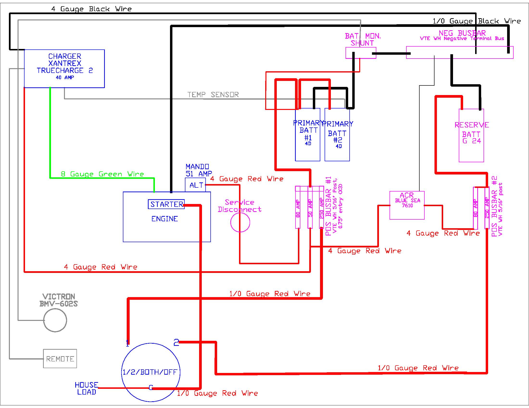
So, with a huge amount of help from MaineSail (aka Compass Marine) I finally settled on the wiring diagram below.

This weekend my brother-in-law, Jason, and my friend, Tom from Sunshine, spent the weekend with me running wires, designing the law out of the new system, fixing the install of the battery charger I did in 2011 and cutting and replacing more zipties than one could imagine.
Jason is the smallest of the group. So he got the unpleasant job of being the troll int he back cave, between the water heater and the holding tank. After a couple of hours of work, he had remounted the charger, disconnected and removed for reuse the 4 gauge red wire that had been for battery #2, added a case ground I had neglected to install in 2011, ran the cable for the remote panel and the batter temperature sensor into the main cabin and reconnected the whole area with zip ties. Here is final look of the charger (forgot to take a before picture).

While Jason was stuck in the cave, Tom was installing the charger remove, battery monitor control unit and a 12 volt double USB charger at the navigation station. Here is what he started with at the nav. station.

Tom is a phenomenal craftsman and laid out the area perfectly. Here is what the area looked like after the installation.

Meanwhile, I was working with the batteries. I disconnected the batteries, remove the existing fuse blocks and lifted the heavy ass 4Ds out of the battery box. Here is what the battery box looked like when we started.

After remove the batteries, I figured out that someone, either the previous owner or the deal who commissioned the boat, had added a battery box. However, when they did this, they put several holes in the box in an attempted to screw it down. Here is a shot of the empty battery box.

So I patch the wholes and rescrewed down the box, bedding the screws to keep the box water tight.
Next, the three of us pondered how to set up a sheet of starboard to serve as the mounting surface for the components of the new system. Did I mention Tom is really good a building things? Well he was able to convert a piece of 3/16-inch by one-inch aluminum bar into a professional looking bracket to hold the starboard at a perfect angle between the battery box and settee. Here are a couple of photos.


That was a great place to end Saturday.
On Sunday, the three of us spent most of the day just trying to figure out how to layout the board to optimize the space on the starboard. In the end, I was happy with the layout, it took up a little more space than I had initially thought it would and there is no space for a solar controller that I plan to add later. Here are a couple of shots.


Obviously I still have to do all of the terminals. I am borrowing a professional grade crimper for that project but I forgot to get it from my friend John before he left for the Bahamas. He runs the parts and service department at a local boat dealer and I will be getting the group 24 reserve battery from him as well. The group 24 reserve battery will be installed in the adjacent settee storage, as suggested by Tom J a fellow C310 owner.
I also will be putting a bus bar near the engine for the grounds instead of stacking up too many connections right to the block. I started to look at that but no real progress yet to show.
I will post an update with the final photos once complete.
UPDATE – March 5th – Batteries by the Numbers
Thanks to this project my primary bank will now consist of two Interstate Deep Cycle/Cranking 12 volt SRM-4D Batteries. The batteries are each 21 inches long by 8 1/4 inches wide by 10 3/8 inches high and weigh 119 pounds (ouch). They can produce 1314 cold cranking amps and have a 190 Ah capacity each. So the new primary bank should have 380 Ah capacity.
I emailed Interstate and their Engineering and Technical Services Specialist replied within an hour that the Peukert number for these batteries is 1.39. Very impressed by the quick response and the engineer gave me his cell number incase I have any problems.
With this, I now have what I need to program my battery monitor.
Looking at my charging systems. I have a 55 amp alternator that was stock with my boat. That is getting rebuilt as part of this project. That would take almost 4 hours (assuming 100% efficiency, which is not very likely) to recharge my system from 50% state of charge. So my current alternator is sized at approximately 14% of the system while 25% is generally recommended. I don’t like that, so I will have to see how long it takes to bring the bank down to 85% state of charge since that will only take an hour or so to recharge. Hopefully that can work for now. Later I plan to add some solar panels which will help with my charging away from the dock.
As far as shore power charging, I have a Xantrex TRUECharge2 40 Amp. Again assuming 100% efficiency, this should be able to recharge my system from a 50% state of charge in about 5 hours. In other words the system is sized at about 10% of the system. This should be OK. If I want to charge off of a generator I may decide to increase to a 60 amp charger.
UPDATE – March 7th – Cost & Final Wiring Diagram
So here is the final wiring diagram for this project.
And here is the final cost.

*I went to the Defender sale this past weekend. I spent another $25 on this project in some additional red 1/0 gauge wire and fittings.
UPDATE – April 10th – More Complete
The system is working but I haven’t added the reserve battery. Everything is wired for the reserve battery but I still need to glass in a shelf below the settee for the battery to sit on and then just connect the reserve battery. Here is a photo of the system completed.

Both the remote for the battery charger and the battery monitor are working great. I can’t wait to spend some time with this system over the summer and figure out what our electrical budget really is for when we go cruising.

Pingback: Two Comfort/Entertainment Upgrades | s/v Smitty
June 10, 2013 at 5:10 am
Well done! I still, after all this time, don’t understand our electrical systems. I really wish I was as knowledgeable as you are!
June 10, 2013 at 5:23 pm
Thanks! It’s not something I knew a lot about before buying our current boat. Lots of hours on the internet.
Can’t wait for your clipper ship stories.
Jesse
September 17, 2013 at 5:50 am
Hi and thanks for these details. I’m headed towards a similar upgrade and am hoping you can answer a few questions. The parts list versus the More Complete pic.
– Where are the positive bus bars in the pic?
– The metal bar tying together the three ANL fuse holders…got a part number for that?
– I don’t see the ANL fuse holders in the parts list.
– how is the VTE gear holding up in the marine environment?
Thanks a bunch.
September 18, 2013 at 12:59 pm
Hi, thanks for reading.
– The red ANL fuse holders with the bar actually make up the positive bus bar. From there it feeds the distribution panel.
-The bar is aluminum in the photo but the permanent one is copper. You have to make that yourself. You can get the bar stock from McMaster Carr. Mine is 3/8″ thick copper.
– The ANL fuse holders are included in the positive bus par cost. The are around $6 each.
– The VTE fuse holders are great and about 1/4 of the price of the Blue Sea Systems. Don’t waste your money on the VTE ANL fuses. Just get the Blue Sea Systems fuses; they fit in the VTE holders fine. We had the VTE fuse fail on a cruise to Maine and the alternator wasn’t charging the batteries because of the failed fuse. The fuse looked fine but no current was passing by it. There is also more current drop than with the Blue Sea System fuses.
Let me know if you have any other questions.
Jesse
Pingback: Battery Upgrade « s/v Smitty
February 12, 2015 at 4:18 am
Hi, great post. I’m just at the wiring/charging stage of re-powering so this is great!
So, almost a year and a half later, would you have done anything different? (have heard some bad things about Zantrex).
I have an S&S classic 37 used mostly on the weekends and a couple of 10-14 day cruises a year. We have very low demands for electricity and rarely use shore power. Would you say it’s too much? It’s soooo tempting to just take the parts list to the store and use the diagram and just copy the whole damn thing!!!!
Any help or advice would be greatly appreciated. Thanks!!!
February 12, 2015 at 4:19 am
*Xantrex*
February 12, 2015 at 7:07 pm
The Xantrex charger is OK. No major issues. I would probably go with a better brand if I were to do it again. Maybe a Sterling.
The bigger issue is the size. The 40 amp charger is just barely big enough for my bank. I wish I had gone bigger. But the 40 amp was all that was available at the time.
No issues with the rest of the system. Very happy with the upgrade.
Good luck,
Jesse